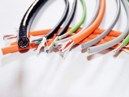
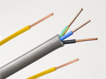
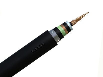
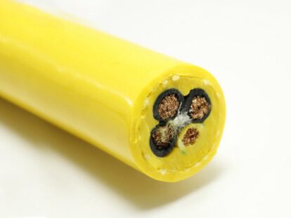
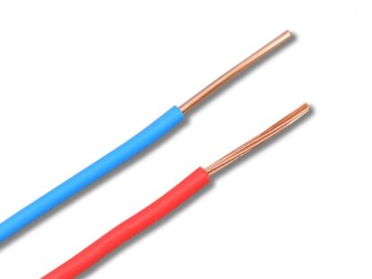
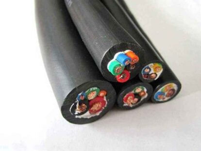
In terms of the ampacity of copper core cables and aluminum core cables and the ampacity of other media, copper core cables and aluminum core cables are very suitable for current industrial wiring and home use. Due to their electrical conductivity and economical applicability, copper core cables and aluminum core cables have become the mainstream of the market.
What is the ampacity of wire and cable?
- Carrying capacity: Under specified conditions (laying conditions; temperature conditions), the conductor can continuously carry (non-short circuit) without causing its stable temperature (burning out if it is too high) to exceed the specified value (the highest temperature of the insulator) The maximum current .
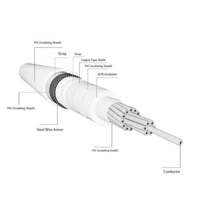
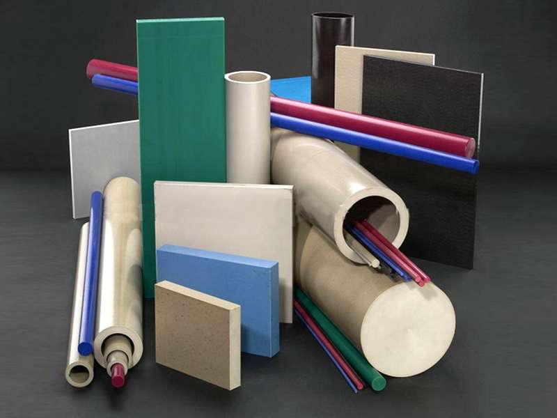
- Insulating material: The materials attached to the copper core and aluminum core cables generally include PVC (polyethylene), XLPE (cross-linked ethylene), EPR (ethylene-propylene compound paste), minerals, etc.
- Standard cross-sectional specifications of general cables (square mm): 0.3; 0.5; 0.75; 1; 1.5; 2.5; 4; 6; 10; 16; 25; 35; 50; 70; 95;
Cable Ampacity Requirements
It is determined according to the allowable core temperature, cooling conditions, and laying conditions, and the ampacity under different conditions is completely different.
The ampacity of aluminum core and copper core cables can be calculated according to the section, and the cross-sectional area of the copper core and aluminum core of the cable can also be calculated according to the current.
Factors Affecting Cable Ampacity
- Ambient temperature
The ambient temperature value adopted is the temperature of the surrounding medium when the cable or conductor under consideration is not loaded.
- Soil thermal resistivity
For cables buried in the ground, where the actual soil thermal resistivity is higher than 2.5K.m/W, the ampacity must be appropriately reduced or the soil close to the cable must be replaced with more suitable materials.

- Multi-loop grouping
When installing more wires or cables in the same group, the specified correction factor must be multiplied. The group correction coefficient is calculated based on the assumption that the cable load of each circuit in the group is the same
- Number of loaded wires
The number of conductors to be considered in a circuit is those carrying the load current. When it can be assumed that the conductors in a polyphase circuit carry balanced currents, their neutral conductors need not be considered. When the neutral wire carries current without a corresponding reduction in the load on the phase wires, the determination of the loop current rating shall take the neutral wire into account. Conductors used only as protective conductors (PE conductors) shall not be considered. The PEN wire should be considered the same as the neutral wire.
- Parallel wires
When two or more wires are connected in parallel in the same phase or pole of the system, measures should be taken to ensure that the parallel wires share the load current evenly.
- Changes in laying conditions along the route
When the cooling conditions of each part of the wiring path are different, the determination of the ampacity should be suitable for the most unfavorable part of the path.
- Insulation material
The current carrying capacity of different insulating materials is different, please refer to the national standard for details.
Cable ampacity table
| Copper | Copper | Copper | Aluminum | Aluminum | |
| Wire Gauge Size | 60°C (140°F) NM-B, UF-B | 75°C (167°F) THW, THWN, SE, USE, XHHW | 90°C (194°F) THWN-2, THHN, XHHW-2, USE-2 | 75°C (167°F) THW, THWN, SE, USE, XHHW | 90°C (194°F) XHHW-2, THHN, THWN-2 |
| 14 | 15 | 20 | 25 | --- | --- |
| 12 | 20 | 25 | 30 | 20 | 25 |
| 10 | 30 | 35 | 40 | 30 | 35 |
| 8 | 40 | 50 | 55 | 40 | 45 |
| 6 | 55 | 65 | 75 | 50 | 55 |
| 4 | 70 | 85 | 95 | 65 | 75 |
| 3 | 85 | 100 | 115 | 75 | 85 |
| 2 | 95 | 115 | 130 | 90 | 100 |
| 1 | --- | 130 | 145 | 100 | 115 |
| 1/0 | --- | 150 | 170 | 120 | 135 |
| 2/0 | --- | 175 | 195 | 135 | 150 |
| 3/0 | --- | 200 | 225 | 155 | 175 |
| 4/0 | --- | 230 | 260 | 180 | 205 |
| 250 | --- | 255 | 290 | 205 | 230 |
| 300 | --- | 285 | 320 | 230 | 260 |
| 350 | --- | 310 | 350 | 250 | 280 |
| 500 | --- | 380 | 430 | 310 | 350 |
| 600 | --- | 420 | 475 | 340 | 385 |
| 750 | --- | 475 | 535 | 385 | 435 |
| 1000 | --- | 545 | 615 | 445 | 500 |
At present, the proportion of electrical fires is increasing rapidly, and a considerable part of them is caused by faults such as insulation damage of cables and wires, overheating and spontaneous combustion, poor contact, single-phase grounding of cables, and short-circuit between phases. Therefore, how to use cables and wires scientifically and reasonably, accurately select the ampacity of cables and wires, and manage and maintain them in compliance with regulations is very important.


